Sunday, June 22, 2008

Making a DNA model!

Constructing a DNA modelThe FIB 10JGo class constructed a DNA model that could be stretched from the third storey in our school all the way down to the first storey, almost touching the ground (see photo below). For the construction, we made about 200 small circular phosphate molecules, 200 pentagonal sugar molecules and 400 rectangular base molecules!!


It was a fun and lively activity, but we did learn a lot about DNA. Or at least, we could cope well with Ms. Carter’s questions afterwards.
DNA stands for deoxyribonucleic acid. We are familiar with DNA in relation to inheritance. For example, we know that DNA has something to do to why offspring often have their parents’ characteristics. Well, that’s correct because DNA is a nucleic acid molecule that carries genetic instructions that is found in all living organisms except some viruses.
In cells of eukaryotic organisms (which have a nucleus in their cells), DNA is found inside the nucleus. Animals (humans are included here), plants, fungi and protists are eukaryotes, so they have their DNA inside their nucleus. Since bacteria do not have a nucleus, they are prokaryotes and their DNA is found in cytoplasm.Now, look at the photo below. It’s a close-up look at our DNA model. The colourful rectangles represent base molecules and contain either one of these letters: T, A, G or C. T stands for thymine, A for adenine, G for guanine and C for cytosine. Notice that T only pairs up with A and G with C. This is the rule of base pairing, i.e. the bases will always pair up this way. Each pair of bases is held together by hydrogen bonds (see the staple between two bases).


The DNA model above looks like a ladder. The phosphates (represented by the yellow circles) join up with sugar molecules (the pentagons) and they make up the uprights of the ladder; the bases make up the rungs. We further twisted the model above into a beautiful double helix (the molecular structure of an actual DNA molecule), so it looked like a spiral staircase.


Petrus Bosa Layarda

Sunday, May 11, 2008

Year 9 research: Cutting edge applications of nanotechnology

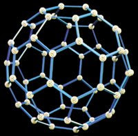
Diamond and graphite are two well-known forms of carbon. In 1985 scientists discovered a third form of carbon based on 60 atoms bonded in a football-like structure. Scientists called this 'buckminsterfullerene', or 'buckyball'. This started a search for other carbon structures. In 1991 a Japanese scientist called Sumio Iijima found carbon nanotubes. These are about 10 000 times thinner than a human hair, made from carbon atoms bonded in sheets and rolled into tubes. Scientists are working to find out more about carbon nanotubes and what they could be used for.
What do nanotubes look like?
Images Top to bottom: carbon nanotubes, a colored image of a nanotube, a ‘buckyball’

Year 9 have been researching the current applications of nanotubes and other areas of nanotechnology - the science of building machines at sub-atomic level.


Scott Heng, Paul Wong, Scott Lim and Qin Yi researched the most recent applications of nano-tubes and discovered that they are 50 times stronger than steel and are currently being developed as molecular sized wires in electronic circuitry. They explained how these molecular sized nano-wires are currently being developed to produce miniature gadgets.


Maria, Antonia and Nicole discovered that a microscopic layer of titanium dioxide (so thin it is invisible) is being used to coat clothing. This titanium oxide reacts with oxygen, creating a chain reaction that eventually results in the removal of dirt particles without washing. As the girls pointed out ‘great for busy people who don’t have time to clean!’


Anthony, Yuan Min and Ian researched the use of nano-sized particles of zinc oxide in sunscreen. Zinc oxide has been used as sunblock for many years, though, it has never become popular as it forms thick white patches on the skin. Scientists have discovered that if zinc oxide is particles are arranged in a single nano-sized layer, it is does not scatter visible light and becomes transparent, preventing the formation of an unsightly white layer .

Mrs Kitchener

Sunday, April 27, 2008

Parents take a Science lesson!!

On April 19 prospective Yr 7 parents visited SJI International to see how we teach. They were involved in several lessons from all subjects and the photos below show them engaed in a science lesson. Some made comment that it was the first time they had been in a science lab for more than 30 years! As you can see they seemed to really enjoy being back.


Thursday, April 3, 2008

The scanning electron microscope

The scanning electron microscope (SEM) is capable of creating images of the surfaces of objects at very high magnification. It's amazing the detail that can be seen using this piece of equipment.

Have a look at these images and try to guess what they are of (the answers are at the bottom of this post)


1. (image width approx. 1mm)


2. (image width approx. 0.010mm)

3. (width of bottom image 0.025mm)


4. (image width 1mm)


5. (image width 0.015mm)


Answers:
1. A seed of the tabacco plant
2. Pollen grains from many types of flowers
3. E = red blood cells L=white blood cell
4. The gills of a fish
5. Cholera bacteria

Monday, March 3, 2008

SWEET, VIOLET SACS

Grade 11 Biology HL class has started a practical on an investigation for a more in depth understanding of the process – osmosis.
Osmosis is the movement of water molecules from a region of higher concentration to a region of lower concentration across a partially permeable membrane, so that eventually two solutions will have uniform water potential.

Osmosis is generally about:


A hypotonic solution has a higher water potential than a hypertonic solution.


In our experiment
The objective of our experiment was to prove that osmosis occurs as water molecules move from a hypotonic solution to a hypertonic solution.


Procedures
Step 1: Prepare a cylindrical gas jar with water. Add a few drops of iodine solution so that water turns a visible yellow.
Step 2: Tie one end of the Visking tubing tightly with thread. We need to ensure that there will not be leaks.
Step 3: Using a dropper, insert 3% starch solution to 3/4 of Visking tubing.
Step 4: Insert delivery tube into Visking tubing. We can’t have air bubbles getting into the delivery tube as this will affect the starch solution level in the delivery tube.
Step 5: Tie the other end of the Visking tubing tightly with thread.
Step 6: Using a dropper, add 3% starch solution into delivery tube to ensure that the starch solution level is clear the visible.
Step 7: Rinse the Visking tubing with water lightly to get rid of starch solution that could have accidentally gotten on the external surface of Visking tubing.


Step 8: Using a retort stand, suspend the delivery tube with attached Visking tubing into the gas jar as shown below.


This, however, is a failed experiment because the starch solution is leaking at a very fast rate as seen by the violet trails in the iodine solution. Presence of starch stains iodine violet.


This is how the set-up should look like:


Results

Explanation:
The 3% starch solution in the visking tubing turned dark blue because of the iodine molecules which diffused from the solution in the glass jar into the visking tubing. The iodine molecules moved from a region of higher concentration (outside the visking tubing) to a region of lower concentration (in the visking tubing), thus showing it moved by diffusion.

We also observed that the level of starch solution in the glass tube rose slightly due to the movement of water molecules from the iodine solution into the 3% starch solution by osmosis. This is because water moved from a region of higher concentration of water molecules though the partially permeable membrane (the visking tubing) to a region of lower concentration of water molecules.

The starch molecules did not move out of the visking tubing because starch molecules are too big and cannot diffuse across the visking tubing. Thus, only the contents of the visking tubing turned dark blue because the iodine reacted with the starch.

By Gabriel Woon, Hilda Foo and Joey Lim

Monday, February 25, 2008

View from the bottom

The Physics department is to be found on the ground floor of the new Science block at SJI-International. Mr. Bowen and Mr. Saranam teach Physics to grades 9-11 and Science to grades 7 & 8. Take a look at some of the things that have being going on on the ground floor in the last week…..

Year 10
Year 10 have been trying to figure out electrical circuits and will gladly explain the difference between an emf and a p.d. if you ask nicely. Here they are investigating the relationship between potential difference and current.
Lorraine: Knit one pearl one…
Bryan :Emf or voltage?
Shaun: What’s the (potential)difference?
Year 8
Year 8 have been studying variation and selective breeding. Here they are investigating variation in tomatoes.

Kenny : The investigation is afoot gentlemen!

Thomas: 151,152,153…
Celestine :You missed one!
Thomas : Where? One hundred and forty…..oh no not again!

Year 7
Year 7 have been looking at separating mixtures by filtration and chromatography:

Lots more investigating to do in the coming weeks …wonder what we will discover?

Wednesday, February 6, 2008

Measuring the size of cells

The FIB 10 JGo class under Ms. Carter experimented with plant cells and animal cells. For plant cells, we used onion cells and human cheek cells for animal cells.

The microscopes in the science lab have the magnification power of x10 for the eye piece and between x4, x10 and x40 for the objective lens. The total magnification can be low power (x40), medium power (x100), or high power (x400). We photographed the cells using our mobile phones.

We first experimented with onion cells (top image). We took a very thin layer of the inner surface of an onion, then we put it on a slide, added a drop of water, and lowered down the cover slip. We looked at the cells under low power and medium power.

With the cheek cells (bottom image), we made use of methylene blue stain instead of water because cheek cells are transparent, so we used methylene blue to make it more obvious. First, we put a drop of methylene blue on the center of the slide. Then we wiped the lining of our cheek with a plastic coffee stirrer and then smeared it on the drop of methylene blue. We looked at the cells with medium and high power, because the cells are much smaller compared to the onion cells.

In order to measure the cell length, we have to know the diameter of field of view of the microscope. So, we measured a ruler under a microscope. The diameter of field of view in: low power=4.2mm, medium power=1.6mm, high power=0.6mm.

In the onion cells picture, the magnification is medium, and there are 9 cells in the diameter of the field of view. Therefore the actual size of an onion cell is 0.47mm.

In the cheek cells picture, the magnification is high, but it’s not clear how many cells there are in the diameter of the field of view. So, we printed the photo and measured the length of a cell in the photo. The diameter of the field of view in the photo is 12.1cm and the length of a cell is 1.35cm. Hence, the actual size of a cheek cell is 0.07mm .
Petrus Bosa Layarda